Kiln Geezer 2 - Intermediate Technology Kiln
Kiln Geezer.2 is the working title of the improved version of the original Kiln Geezer,
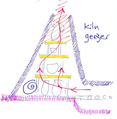
Fig.1 Cut away sketch of the original Kiln Geezer.
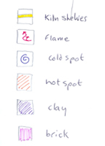
Fig.2 Key for the above sketch.
The original model employed a simple up draught design and introduced a novel method for constructing the kiln walls, but had serious limitations. The short time available for the firing cycles at a festival, necessitated ignoring existing guidelines for the temperature increase gradient and we still produced undamaged fired wares. Numerous ideas arose as a result of these test firings at the Glastonbury Festival and the Big Green Gathering in 1994, including the need to improve efficiency of the kiln, particularly in the heat work obtained from the volume of fuel consumed.
The clay walls utilise a hollow structure which insulates and retains heat in the firing chamber. This characteristic was achieved during the kiln construction through the inclusion of straw into the clay slurry which formed the kiln and was applied in layers onto an open wicker framework. This framework burned away during the test firing to leave thousands of small air spaces in the kiln walls. The new design retains this hollow structural element but improves on the earlier, simple, up draught model by employing a more complex down draught technique.
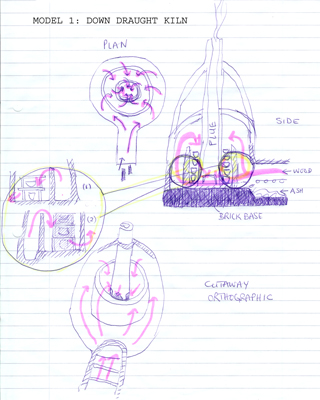
Fig.3 Rough sketches exploring possible kiln architectures.
A down draught design has the intention of getting better heat work out of the fuel consumed by keeping the flames in the kiln longer. However, the design above has several limitations, for one, the central chimney flue limits the space available for wares.
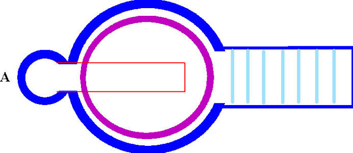
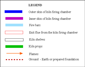
Diagram A Plan View - cross section. Drawn at (roughly) ground level, showing the chimney flue at left. The central section shows the outer kiln wall, the inner wall of the firing chamber and the exhaust flue shaft set into the chamber floor and connecting with the base of the chimney. At right the fire box with fire bars.
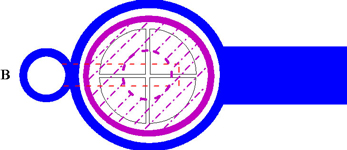
Diagram B Plan View cross section drawn at a higher level, showing the inner chamber with kiln furniture in place.
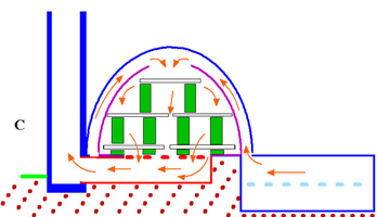
Diagram C Side View cross section along the centre line, showing the gap in the top of the inner firing chamber, kiln furniture and the direction of the flames.
Next are photos of the kiln construction which began in the summer of 2010.
Follow this link Kiln Geezer Page 3

